Project Overview
I'm building an autonomous chess board that physically moves pieces to play against a human opponent. no screens, no manual input, just a traditional chess experience where the computer moves its own pieces. This ongoing project combines computer vision, robotics control, embedded systems, and mechanical design into one integrated system.
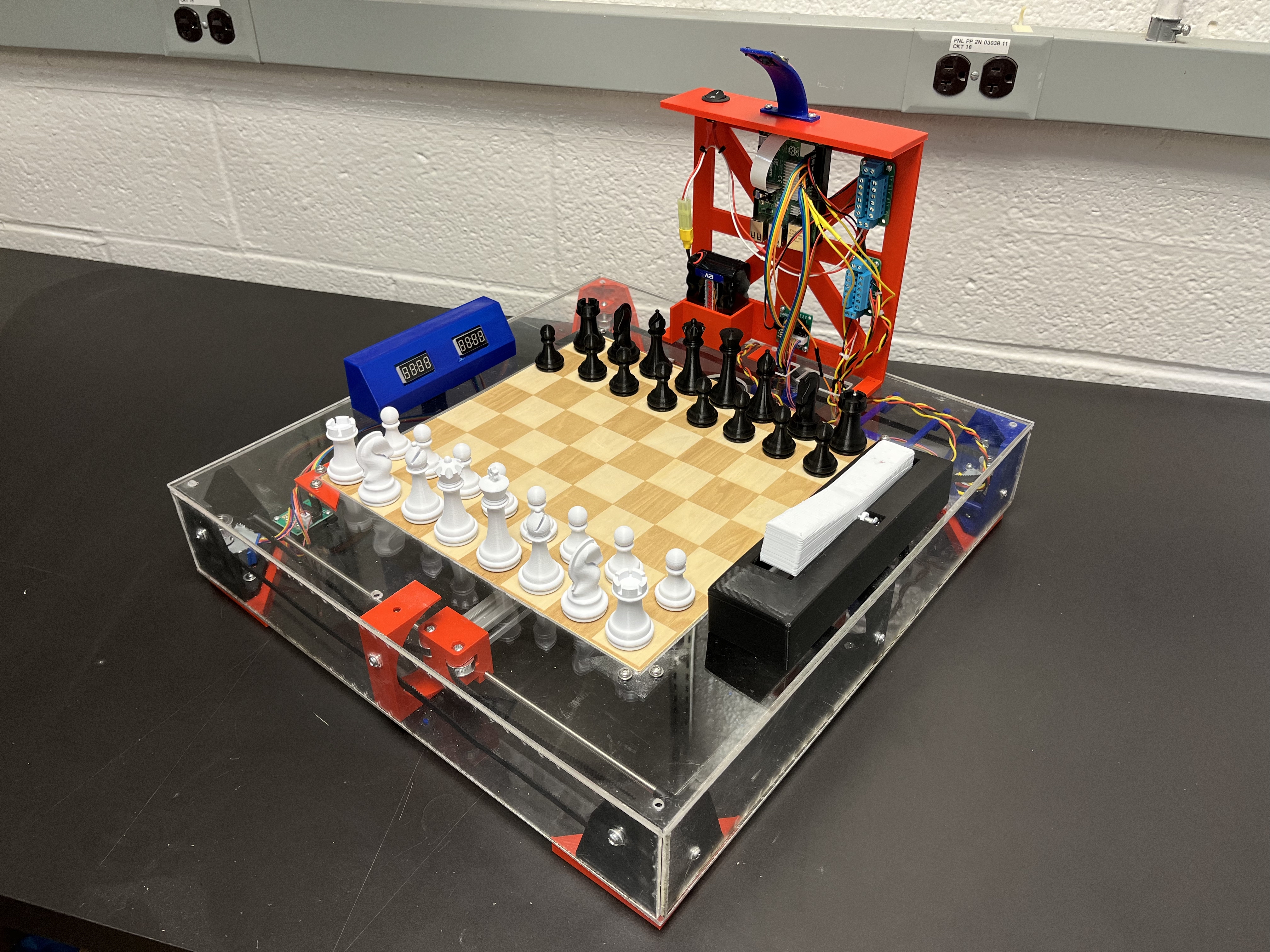
The board uses a Raspberry Pi for processing, an overhead camera for board state detection, a Python chess engine for move calculation, and a custom CoreXY gantry system with a servo-actuated magnet to physically move pieces from beneath the board. A traditional chess clock provides timing and serves as the trigger mechanism. when the human player hits their side of the clock, it signals the system to capture the board state, calculate its move, and execute.
Project Status: Currently in active development (2 semesters in progress). Hardware assembly is largely complete, with motors operational. Software integration and computer vision pipeline are the next major milestones.
Current hardware assembly with CoreXY gantry and electronics
Design Goals
This isn't just about moving chess pieces, it's about creating an authentic chess-playing experience against a computer opponent that feels like playing against another person. The board maintains the tactile, focused nature of traditional chess while incorporating autonomous capabilities.
Core Requirements:
- Seamless gameplay: Human moves piece → hits clock → computer moves piece
- Reliable piece detection: Track all 32 pieces across 64 squares in real-time
- Precise motion: Move pieces accurately without collisions or drops
- Standard chess interface: Regular pieces, standard board, traditional clock
System Architecture
Hardware Components
Mechanical System:
- CoreXY gantry with 14"×14" working area (larger than 12"×12" board for edge access)
- 2020 aluminum extrusion frame (18"×19" outer dimensions)
- Belt-driven X-Y motion with stepper motors
- Servo-actuated magnet end effector (rotates 90° to engage/disengage pieces)
Electronics:
- Raspberry Pi 4: Main controller running ROS
- Stepper motors: NEMA 17 for X and Y axes
- Servo motor: Magnet actuation
- Camera: Raspberry Pi Camera Module (overhead mount)
- Chess clock: Player input trigger (wired to GPIO)
Board Construction:
- Laser-cut wood chessboard (engraved squares)
- Clear acrylic outer casing (laser cut)
- 3D printed PLA brackets, mounts, slider rails, camera mount
SolidWorks assembly showing complete mechanical design
Mechanical Design & Manufacturing
CoreXY Gantry System
I selected a CoreXY configuration because both motors remain stationary (mounted to the frame), reducing moving mass compared to traditional Cartesian systems. This allows for:
- Higher speeds (less inertia to overcome)
- Better accuracy (motors don't shift weight distribution during motion)
- Symmetrical belt routing (equal precision in both axes)
CoreXY belt routing with stationary motors
Custom 3D Printed Components
This is my first major SolidWorks project, and I've designed every custom component from scratch:
Key Parts Designed:
- Motor mounting brackets
- Belt tensioners (adjustable design)
- Slider rail carriages for X and Y axes
- Camera mounting system (adjustable height and angle)
- Electronics enclosures
- Servo mount with magnet holder
Design Challenges:
- Tolerance management: 3D printed parts require clearances (typically 0.2-0.3mm) for smooth motion. Learning to account for printer tolerances in the CAD model was critical.
- Structural rigidity: Ensuring brackets don't flex under belt tension or acceleration loads
- Iterative refinement: Multiple print iterations to achieve proper fits. This project taught me to design for manufacturability
Material Choices:
- PLA for everything mechanical: Fast iteration, easy to print, sufficient strength for this application
- Clear acrylic for casing: Laser cut for clean edges, allows visibility into mechanism
- Wood for chessboard: Traditional aesthetic, laser engraved for square definition
Sample of custom 3D printed brackets and mounts
Learning SolidWorks
This project forced me to learn advanced CAD modeling:
- Assembly constraints: Managing dozens of parts with proper mates
- Tolerance stack-up: Understanding how small errors compound across assemblies
- Design for assembly: Making parts that can actually be assembled in the real world
- Parametric design: Using variables so changes propagate through the model
Creating a high-fidelity model that I could actually build from was a major milestone. The CAD model serves as the single source of truth for all dimensions, hole placements, and assembly procedures.
Computer Vision Pipeline (Planned)
The vision system is the brain of the operation, but it's still in the design phase. Here's the planned approach:
1. Camera Calibration
- Use checkerboard pattern to correct lens distortion
- Establish transformation from camera coordinates to board coordinates
2. Board Detection
- Canny edge detection
- Hough line transform to find the 64-square grid
- Establish perspective transformation for top-down view
3. Piece Detection
- Color segmentation (HSV color space) to distinguish black vs. white pieces
- Contour analysis to locate piece positions (find blobs)
4. State Tracking (Key Innovation)
Instead of trying to identify piece types visually (computationally expensive and unreliable), the system:
- Knows the starting position (standard chess setup)
- Tracks which blobs move between frames (before/after player move)
- Uses chess engine to validate that the detected move is legal
- Updates internal board state accordingly
Pseudocode:
def detect_board_state(current_frame, previous_frame):
# Find all piece blobs in both frames
current_blobs = find_blobs(current_frame)
previous_blobs = find_blobs(previous_frame)
# Identify which blob moved
moved_blob = find_difference(current_blobs, previous_blobs)
# Determine from_square and to_square
from_square = blob_to_square(moved_blob.old_position)
to_square = blob_to_square(moved_blob.new_position)
# Validate move is legal for piece at from_square
if chess_engine.is_legal(from_square, to_square):
update_board_state(from_square, to_square)
else:
request_player_retry() # Invalid move detectedThis approach is much more robust than trying to do shape-based piece recognition, which fails under varying lighting and viewing angles.
Motion Control System
Current Status
The gantry is mechanically complete and motors are functional. I can send commands to move the X and Y axes. However, the integrated control system (path planning, collision avoidance, coordinated motion) is still being developed.
Planned Motion Planning
Path Planning Algorithm:
def plan_move(from_square, to_square, board_state):
"""
Plan collision-free path from source to destination
"""
# Check if direct path is clear
if is_path_clear(from_square, to_square, board_state):
return [from_square, to_square]
# If destination occupied (capture), remove captured piece first
if board_state[to_square] is not None:
captured_path = move_to_graveyard(to_square)
main_path = [from_square, to_square]
return captured_path + main_path
# Otherwise, plan around obstacles (A* pathfinding)
return find_obstacle_free_path(from_square, to_square, board_state)Motion Execution:
- Shortest path: Minimize move time by finding direct routes when possible
- Collision avoidance: Navigate around occupied squares
- Smooth acceleration/deceleration: Prevent pieces from sliding off magnet
Servo-Actuated Magnet
The end effector uses a servo motor that rotates 90° to bring a magnet close to the underside of the board:
- Engaged (0°): Magnet near board surface, piece sticks
- Disengaged (90°): Magnet pulled away, piece releases
This simple mechanism is more reliable than an electromagnet (no current control needed) and easier to mount on a moving gantry.
ROS Integration (In Development)
The software will be structured as modular ROS nodes:
Planned Node Architecture:
/camera_node → Publishes board state (FEN strings)
/engine_node → Subscribes to board state, computes moves
/motion_node → Subscribes to move commands, controls gantry
/clock_node → Detects clock hits, triggers turn changesBenefits of ROS:
- Modularity: Test each component independently
- Flexibility: Easily swap implementations (different cameras, engines, etc.)
- Debugging: Visualize data flow with and monitor topics live
rqt_graph
I'm still learning ROS as part of this project, so the node structure may evolve as I understand best practices better.
Game Clock Integration
The chess clock serves a dual purpose:
- Timing: Tracks how much time each player has remaining (standard chess timer)
- Turn trigger: When the human hits their side of the clock, it sends a signal to the Raspberry Pi GPIO, indicating "my turn is complete, your turn now"
This creates a natural interaction. Players use the clock exactly as they would in a normal chess game, and it seamlessly triggers the computer's response.
Workflow:
- Human makes move on board
- Human hits chess clock
- GPIO interrupt triggers on Raspberry Pi
- Camera captures image
- Vision system detects move
- Chess engine calculates response
- Gantry executes computer's move
- Clock switches back to human's time
Digital Twin (Early Stage)
I've created a preliminary NVIDIA Isaac Sim model of the chess board to:
- Validate mechanical kinematics (ensure gantry can reach all squares)
- Test motion planning algorithms before hardware integration
- Visualize the complete system
Current Status: Basic model exists but needs refinement. The digital twin will become more valuable once the vision and control systems are operational, allowing full simulation-to-reality validation.
Early-stage Isaac Sim digital twin (being refined)
Technical Challenges
1. First-Time SolidWorks User
This project was my introduction to professional CAD software. Challenges included:
- Learning assembly mates and constraints
- Understanding tolerance stack-up across multi-part assemblies
- Designing for 3D printing (support material, overhangs, print orientation)
- Iterating designs without breaking downstream dependencies
Impact: Gained proficiency in a critical engineering tool. The final CAD model is detailed enough to manufacture from without additional drawings.
2. 3D Printing Tolerances
Achieving smooth motion in the gantry required learning how to design for FDM printing:
- Accounting for ±0.2mm dimensional variation
- Designing adjustable belt tensioners (can't predict exact belt stretch)
- Iterating slider rail clearances (too tight = binding, too loose = wobble)
Solution: Design with adjustability in mind. Slots instead of holes, tensioners with range, multiple test prints to dial in fits.
3. Electronics Integration (Ongoing)
Current Challenge: Wiring all components cleanly and reliably. I'm using off-the-shelf boards (no custom PCB), so cable management and connector reliability are critical.
Approach:
- Document every connection with electrical schematics
- Use terminal blocks for easy debugging/rewiring
- Test each subsystem independently before full integration
4. Computer Vision (Upcoming)
Anticipated Challenges:
- Variable lighting: Room lighting affects piece detection. I may need to add LED illumination
- Piece occlusion: Pieces partially blocking each other during movement
- Calibration drift: Camera may shift slightly during operation
Planned Solutions:
- Implement adaptive thresholding based on ambient light
- Use temporal filtering (multiple frames) to reduce noise
- Periodic re-calibration routine
Current Status
✅ Completed
- Mechanical design: Full SolidWorks assembly with all custom parts modeled
- Hardware fabrication: All 3D printed and laser-cut components manufactured
- Frame assembly: 2020 extrusion frame built, gantry assembled
- Motors operational: Stepper motors respond to commands (no coordinated motion yet)
- ROS environment: Raspberry Pi configured with ROS installed
🔨 In Progress
- Electronics wiring: Connecting all components to Raspberry Pi
- Motor calibration: Tuning steps-per-mm for accurate positioning
- Camera alignment: Mounting and aligning overhead camera for optimal view
📅 Coming Next (Priority Order)
- Get gantry moving smoothly: Write ROS nodes for coordinated X-Y motion
- Test magnet pickup: Verify servo-magnet system reliably grabs/releases pieces
- Implement vision pipeline: Get basic piece detection working
- Integrate chess engine: Connect Python chess library to board state
- Full system test: Complete human-vs-computer game
What I'm Learning
This project is teaching me system integration at a level I haven't experienced before:
Mechanical Engineering:
- CAD modeling with SolidWorks (parametric design, assemblies, tolerances)
- Design for manufacturing (FDM printing constraints, laser cutting)
- Mechanism design (belt systems, linear motion, actuators)
Software Engineering:
- ROS architecture (nodes, topics, publish-subscribe patterns)
- Computer vision (OpenCV, image processing pipelines)
- State machine design (managing game flow, error handling)
Electrical Engineering:
- Motor control (stepper drivers, PWM, GPIO)
- System wiring (power distribution, signal routing)
- Sensor integration (camera, switches, encoders)
Project Management:
- Breaking down a large project into achievable milestones
- Collaborating with a teammate on a complex system
- Iterating designs based on testing feedback
Most Important Lesson: Integration is harder than implementation. Each subsystem works in isolation, but making them work together reliably requires careful interface design, robust error handling, and extensive testing.
Future Enhancements
Once the core system is operational, potential additions include:
Software Features:
- Adjustable difficulty: Multiple chess engine strength levels
- Online play: Connect to chess.com API for remote opponents
- Game analysis: Post-game move annotations and suggestions
- Tournament mode: Multi-game sessions with ELO tracking
Hardware Improvements:
- LED board illumination: Improve vision reliability, highlight last move
- Piece detection confirmation: Small sensors under each square (capacitive or Hall effect)
- Faster motion: Optimize acceleration profiles for quicker games
Technologies Used
Mechanical Design: SolidWorks (first major project)
Manufacturing: FDM 3D Printing (PLA), Laser Cutting (Acrylic, Wood)
Electronics: Raspberry Pi 4, NEMA 17 Stepper Motors, Servo Motor
Software: Python, ROS (Noetic), OpenCV (planned), Python Chess Engine
Development Tools: VS Code, Docker, Git
Simulation: NVIDIA Isaac Sim (early-stage digital twin)
This project is ongoing and represents my most ambitious engineering effort to date. I am integrating mechanical, electrical, and software systems into one cohesive product. Follow the GitHub repository for updates as development continues.
