Autonomous Fire Truck

ArduinoSolidWorks3D PrintingAutonomous SystemsC++

Project Overview

For my introduction to engineering course, my team was challenged to design, build, and program a fully autonomous robot capable of navigating difficult terrain, detecting fires, determining topography, and extinguishing specific candles—all without human intervention after the start signal.

As mechanical lead and primary programmer, I designed the robot's unique folding platform extinguishing system, integrated all sensors, and implemented the state-machine control logic in Arduino C++. The result was a robot that successfully completed all mission objectives in under 2 minutes.

Fire Truck Final Design 
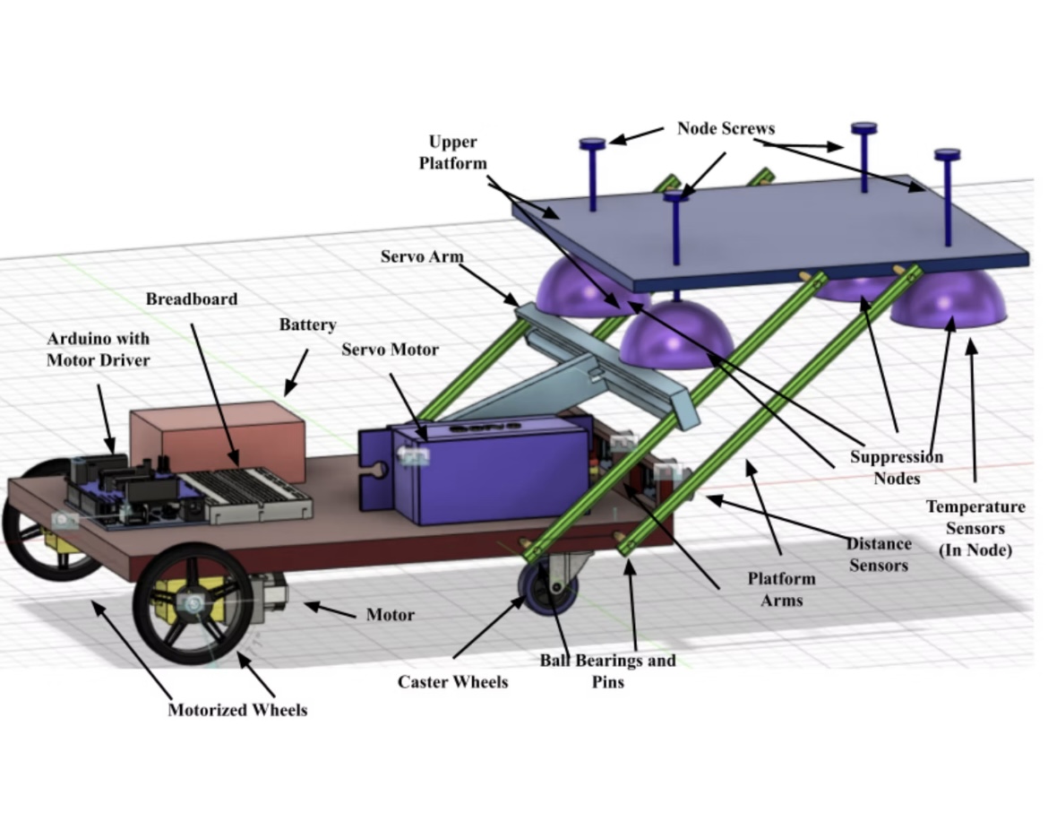
Final autonomous fire truck with extended suppression platform


Mission Objectives

The robot must autonomously:

  1. Topography Sensing: Determine the orientation of a block with candles at varying heights (sides A, B, or C)
  2. Fire Sensing: Count the number of lit candles on the block
  3. Fire Suppression: Extinguish all candles except the center candle
  4. Localization & Navigation: Use an overhead camera system to navigate to target locations on a 10'×10' arena

Scoring: Points awarded for accuracy and speed. Incorrect topography detection = disqualification.

Mission Arena Competition arena layout with obstacles and target zones


Design Philosophy

Mechanical Innovation: Folding Platform System

Traditional approaches used fixed water nozzles or fans. I designed a mechanically actuated suppression platform that:

Platform Mechanism Animation showing platform extension and retraction

Why This Works:

Electronic Architecture

The robot uses an Arduino Uno as the central controller, coordinating:

Sensors:

Actuators:

Electronics Diagram Complete electrical schematic showing all connections

Power Management:


Technical Implementation

1. Topography Sensing

The candle block has three possible orientations, distinguished by height differences:

Topography Variants Three possible block orientations (A, B, C)

Sensing Strategy:

I mounted two ultrasonic sensors at specific heights to measure distances to the center and right portions of the block.

// Topography detection algorithm char detectTopography() { float centerDist = readUltrasonic(CENTER_SENSOR_PIN); float rightDist = readUltrasonic(RIGHT_SENSOR_PIN); float diff = centerDist - rightDist; if (diff < -THRESHOLD) { return 'A'; // Center closer than right (high center) } else if (diff > THRESHOLD) { return 'B'; // Center farther than right (low center) } else { return 'C'; // Center same as right (flat) } } float readUltrasonic(int trigPin) { // Trigger ultrasonic pulse digitalWrite(trigPin, LOW); delayMicroseconds(2); digitalWrite(trigPin, HIGH); delayMicroseconds(10); digitalWrite(trigPin, LOW); // Measure echo time long duration = pulseIn(trigPin + 1, HIGH, TIMEOUT); // Convert to distance (cm) float distance = duration * 0.034 / 2; return distance; }

Validation: Tested on 50+ measurement cycles with 100% accuracy.

Ultrasonic Mounting Custom 3D printed mounts position sensors at correct heights

2. Fire Sensing

Each of the four suppression nodes contains a DHT20 temperature sensor. When positioned over a candle, the sensor detects elevated temperature.

Detection Algorithm:

int countFires() { int fireCount = 0; float ambientTemp = readAmbientTemperature(); // Baseline from IMU // Check each suppression node for (int i = 0; i < 4; i++) { float temp = dht[i].readTemperature(); // If temp > 10°C above ambient, candle detected if (temp > ambientTemp + FIRE_THRESHOLD) { fireCount++; } } return fireCount; }

Challenge: Sensors heat up from proximity to previously extinguished candles (residual heat).

Solution:

3. Fire Suppression

The suppression platform uses four aluminum-foil-wrapped nodes suspended on 3D printed rods with ball joints.

Suppression Nodes Four suppression nodes with flexible suspension

How It Works:

  1. Platform extends over block (servo rotates arm)
  2. Nodes lower onto candles (gravity + flexible rods)
  3. Foil cups smother flames (oxygen deprivation)
  4. Center hole ensures middle candle untouched
  5. Platform retracts after 5-second dwell time

Mechanical Design:

The platform is supported by four acrylic beams that rotate on ball bearings (8 total). A servo-driven arm pulls two beams via zip-ties, causing the entire platform to fold.

void extinguishFires() { // Extend platform platformServo.write(EXTENDED_ANGLE); // 90 degrees delay(3000); // Allow platform to fully extend // Wait for extinguishment delay(5000); // 5 seconds to smother flames // Retract platform platformServo.write(RETRACTED_ANGLE); // 0 degrees delay(3000); }

Platform CAD SolidWorks model showing platform mechanism and servo arm

4. Localization & Navigation

The robot uses an ArUco marker on its top surface, visible to an overhead camera system that provides real-time position and orientation.

Position Data Format (received via WiFi):

struct Position { float x; // X coordinate (meters) float y; // Y coordinate (meters) float theta; // Heading angle (radians) };

Navigation Controller:

I implemented a simple proportional controller for waypoint following:

void navigateToWaypoint(float targetX, float targetY) { while (distanceToWaypoint(targetX, targetY) > WAYPOINT_TOLERANCE) { // Get current position from camera Position current = updatePosition(); // Calculate desired heading float desiredHeading = atan2(targetY - current.y, targetX - current.x); float headingError = normalizeAngle(desiredHeading - current.theta); // Proportional control int leftSpeed = BASE_SPEED - (int)(KP_TURN * headingError); int rightSpeed = BASE_SPEED + (int)(KP_TURN * headingError); // Constrain speeds leftSpeed = constrain(leftSpeed, -MAX_SPEED, MAX_SPEED); rightSpeed = constrain(rightSpeed, -MAX_SPEED, MAX_SPEED); // Apply to motors setMotorSpeeds(leftSpeed, rightSpeed); delay(50); // 20 Hz control loop } // Stop at waypoint setMotorSpeeds(0, 0); }

Tuning: Adjusted

KP_TURN
gain through trial-and-error testing to minimize overshoot while maintaining responsiveness.

Navigation Test Recorded path showing waypoint following accuracy


Software Architecture: State Machine

The robot's behavior is controlled by a finite state machine that sequences mission tasks:

enum State { IDLE, NAVIGATE_TO_BLOCK, DETECT_TOPOGRAPHY, APPROACH_BLOCK, SENSE_FIRES, EXTINGUISH, RETREAT, MISSION_COMPLETE }; State currentState = IDLE; void loop() { switch (currentState) { case IDLE: // Wait for start signal if (startButtonPressed()) { currentState = NAVIGATE_TO_BLOCK; } break; case NAVIGATE_TO_BLOCK: navigateToWaypoint(BLOCK_X, BLOCK_Y); currentState = DETECT_TOPOGRAPHY; break; case DETECT_TOPOGRAPHY: char topo = detectTopography(); transmitTopography(topo); // Send to judges currentState = APPROACH_BLOCK; break; case APPROACH_BLOCK: // Fine positioning using ultrasonic feedback approachUntilDistance(TARGET_DISTANCE); currentState = SENSE_FIRES; break; case SENSE_FIRES: int fireCount = countFires(); transmitFireCount(fireCount); currentState = EXTINGUISH; break; case EXTINGUISH: extinguishFires(); currentState = RETREAT; break; case RETREAT: navigateToWaypoint(HOME_X, HOME_Y); currentState = MISSION_COMPLETE; break; case MISSION_COMPLETE: celebratoryBeep(); // Stop execution break; } }

State Machine Diagram State transition diagram showing mission flow

Benefits of State Machine Architecture:


Mechanical Design Details

Drivetrain

Configuration: Differential drive (2 powered wheels + 2 caster wheels)

Wheel Selection:

Drivetrain Design Motor-driven rear wheels with front caster wheels

Motor Specifications:

Platform Mechanism

The folding platform was the most complex mechanical subsystem.

Design Requirements:

Material Selection:

Platform Extended CAD Full CAD model showing extended platform configuration

Servo Sizing:

Suppression Nodes

Each node consists of:

Node Design Cross-section of suppression node showing sensor placement


Testing & Iteration

Prototype Evolution

Version 1: Fixed nozzles spraying water

Version 2: Fan-based air blast

Version 3: Mechanical smothering (final design)

Test Results

Arena Testing (15 full mission runs):

Competition Performance:

Competition Result Robot during competition run


Challenges Overcome

Challenge 1: Sensor Noise

Problem: Ultrasonic sensors gave erratic readings near metal obstacles.

Solution:

float filteredUltrasonic(int pin) { const int SAMPLES = 5; float readings[SAMPLES]; // Collect samples for (int i = 0; i < SAMPLES; i++) { readings[i] = readUltrasonic(pin); delay(10); } // Sort array qsort(readings, SAMPLES, sizeof(float), compareFloat); // Return median return readings[SAMPLES / 2]; }

Challenge 2: Platform Binding

Problem: Platform mechanism occasionally jammed during deployment.

Root Cause: Acrylic beams slightly warped from heat during assembly.

Solution:

Challenge 3: WiFi Latency

Problem: Position updates from camera had 100-200ms latency.

Solution:


What I Learned

Technical Skills

Embedded Systems:

Mechanical Design:

System Integration:

Engineering Process

Iterative Design: Initial concept rarely works perfectly—embrace iteration

Testing is Critical: Spent 50% of project time on testing (paid off with reliable performance)

Documentation: Maintained detailed build log—invaluable during troubleshooting

Team Collaboration: Regular check-ins with team prevented integration issues


Future Improvements

If I were to redesign this robot:

  1. Add obstacle detection: Integrate front-facing distance sensors for collision avoidance
  2. Improve fire sensing: Use IR flame sensors (faster response than temperature)
  3. Upgrade controller: Move to Raspberry Pi for onboard vision processing
  4. Enhance navigation: Implement SLAM for autonomous mapping

Top View Top-down view showing ArUco marker and electronics layout

Electronics Top View Electronics bay showing Arduino, motor driver, and wiring

Electrical Schematic Detail Detailed schematic of power distribution and sensor connections

📹 Full Demonstration Video: Watch complete mission run


Technologies Used

Hardware: Arduino Uno, HC-SR04 Ultrasonic Sensors, DHT20 Temperature Sensors, L298N Motor Driver, Standard Servo, 12V DC Motors
Software: Arduino IDE, C++
Design: SolidWorks 2021, Fusion 360
Manufacturing: FDM 3D Printing (PETG), Laser Cutting (Plywood, Acrylic)
Testing: Serial Monitor, Oscilloscope (motor signal debugging)


This project represents my first complete robotics system—from concept to competition—teaching me the fundamentals of autonomous system design and integration.